
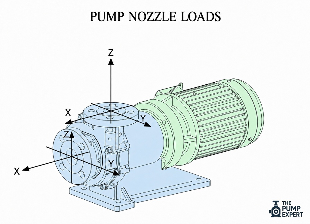
Pump nozzle loads are one of the most common hidden causes of pump reliability problems. A pump may be correctly selected, properly installed, and well maintained, yet still suffer repeated seal failures, bearing wear, vibration, or alignment issues because the connected pipework is forcing the pump casing out of shape.
Nozzle loads, also called flange loads, are the forces and moments applied to a pump’s suction and discharge nozzles by the connected piping. These loads come from pipe weight, thermal expansion, hydraulic pressure forces, installation misalignment, and movement in the surrounding system. Hydraulic Institute guidance describes nozzle loads as forces and moments acting on pump nozzles, with excessive loads capable of causing shaft misalignment and major component failures.
This article explains what nozzle loads are, why they occur, how they affect pumps, and how to control them during design, installation, and maintenance.
What are nozzle loads?
A pump nozzle is the connection point where the pipework bolts to the pump casing. Most pumps have at least two nozzles:
- Suction nozzle: where fluid enters the pump.
- Discharge nozzle: where fluid leaves the pump.
A nozzle load is the external load transferred from the pipework into these connection points.
These loads include both forces and moments. A force pushes or pulls in a straight line. A moment is a twisting or bending load caused by force acting at a distance. In practical terms, the pipe may push down on the pump, pull sideways, twist the flange, or try to rotate the casing.
Nozzle loads are usually assessed in six components at each nozzle:
| Load type | What it means in practice |
|---|---|
| Axial force | Push or pull along the pipe centreline |
| Vertical force | Upward or downward load from pipe weight or movement |
| Horizontal force | Side load from poor alignment or pipe movement |
| Torsional moment | Twisting load around the pipe axis |
| Bending moment | Load trying to bend the nozzle vertically or horizontally |
| Resultant load | Combined effect of multiple forces and moments |
A pump can tolerate some nozzle load. No installation is completely free from external forces. The issue is whether the applied loads stay within acceptable limits for the pump casing, baseplate, supports, and alignment condition.
ANSI/HI 9.6.2-2021 covers assessment of applied nozzle loads for several rotodynamic pump types. It recognises that excessive nozzle loads can cause nozzle stress, internal casing misalignment, rubbing, driver-to-pump misalignment, vibration, and premature bearing or seal failure.
Why excessive nozzle loads occur
Excessive nozzle loads usually come from the piping system, not the pump itself. The pump becomes the fixed point that absorbs forces the pipework should have managed elsewhere.
Poor pipe alignment during installation
A common cause is pipework that does not line up naturally with the pump flanges.
If installers need to pull the pipe into position using flange bolts, chain blocks, jacks, or temporary supports, the pipe is already applying strain to the pump. Once the bolts are tightened, that strain remains locked into the system.
This is often called cold pipe strain because it exists before the system reaches operating temperature.
Good installation practice requires the pipe flange to meet the pump flange without forcing the connection. Hydraulic Institute guidance notes that mechanical pipe strain can result from misaligned piping and assembly tolerances, and that pipe flanges should be close to the pump flanges in the unbolted condition.
Pipe weight and poor support
Pipework should be supported independently of the pump.
If the pump nozzle carries the weight of pipe, valves, strainers, reducers, insulation, or fluid, the casing sees loads it was not intended to carry. This is especially important on large-diameter suction lines, long unsupported pipe runs, and installations with heavy valves close to the pump.
A pump should connect to the pipe system. It should not act as a pipe support.
Thermal expansion and contraction
Pipes expand when they heat up and contract when they cool down. In hot water, steam condensate, chemical process, and thermal oil systems, this movement can be significant.
If the pipework cannot move in a controlled way, thermal growth pushes into the pump nozzles. A system may align well when cold but impose high nozzle loads once it reaches operating temperature.
This is why nozzle load assessment must consider both installation condition and operating condition.
Hydraulic pressure forces
Pressure in the pipework can create axial thrust, especially where the system includes flexible couplings, expansion joints, reducers, elbows, or unrestrained pipe sections.
Expansion joints deserve careful attention. They can help accommodate movement, but an unrestrained expansion joint may create large pressure thrust loads. Those loads can transfer directly into the pump unless tie rods, anchors, guides, and supports are correctly designed.
Hydraulic Institute training material identifies thermal growth, pressurisation strain, installation misalignment, and hydraulic pressure reaction forces from axially flexible pipe couplings as sources of nozzle loading.
How excessive nozzle loads damage pumps
Nozzle loads rarely announce themselves as “pipe strain”. They usually appear as recurring mechanical problems.
Shaft misalignment
External piping loads can distort the pump casing or move the pump relative to the driver. This changes shaft alignment at the coupling.
Misalignment increases vibration and places extra load on bearings, seals, couplings, and hold-down bolts. A pump may be aligned accurately during commissioning, then move out of alignment when the pipework is connected or when the system heats up.
Casing distortion and internal rubbing
A pump casing has internal clearances between rotating and stationary components. Excessive flange loads can distort the casing enough to reduce those clearances.
In severe cases, the rotating element may rub against wear rings, casing components, or internal surfaces. This can increase vibration, raise power demand, damage components, and reduce pump life.
Mechanical seal and bearing failure
Mechanical seals depend on stable shaft position and controlled vibration. Bearings depend on correct shaft alignment and manageable radial and axial loads.
When nozzle loads distort the pump casing or create misalignment, the seal faces may run unevenly and bearings may see loads outside their intended operating range. The result is often repeated seal leakage or bearing failure without an obvious hydraulic cause.
Baseplate and anchor bolt stress
Nozzle loads do not stop at the casing. They can transfer through the pump feet into the baseplate, grout, foundation, and anchor bolts.
This can loosen hold-down bolts, crack grout, distort the baseplate, and make alignment unstable. In some cases, maintenance teams keep realigning the pump without correcting the pipe strain that caused the movement.
Signs of a nozzle load problem
Nozzle load issues can look similar to other pump faults, so diagnosis requires care. Common warning signs include:
- Alignment changes after piping is connected.
- Alignment changes between cold and hot operating condition.
- Pipe flanges move when bolts are loosened.
- Repeated mechanical seal leakage.
- Premature bearing failure.
- High vibration after installation or pipework modification.
- Difficulty inserting flange bolts without forcing.
- Visible strain in pipe supports, guides, or expansion joints.
- Coupling wear without a clear lubrication or installation issue.
A useful field check is to compare alignment before and after pipe connection. Another check is to loosen flange bolts under controlled, safe conditions and observe whether the pipe flange springs away from the pump flange.
This work must follow site isolation, depressurisation, draining, and safety procedures. Never loosen pump flanges on a pressurised or hazardous system.
How to prevent excessive nozzle loads
Nozzle load control starts in design and continues through installation and maintenance.
Design the pipework to support itself
The pipe system should have suitable supports, guides, anchors, and restraints. Supports must carry pipe weight and allow expected movement. Anchors and guides must control thermal expansion without pushing excessive load into the pump.
For hot systems, the piping stress analysis should assess both cold and operating conditions.
Do not use the pump as an anchor
A pump casing is not a structural anchor for the pipe system. The piping design should prevent large thermal, pressure, and weight loads from being resolved through the pump nozzles.
Where expansion joints are used, design the restraints properly. Tie rods, anchors, and guides must manage pressure thrust and movement. A flexible connector installed without load control can create a larger problem than the one it was intended to solve.
Align piping before bolting
The pipe flange should meet the pump flange naturally. The bolt holes should align without forcing, and the flange faces should be parallel within the project tolerance.
Tightening flange bolts should close a gasketed joint. It should not pull the pipe into position.
Check pump alignment after piping is connected
Pump-to-driver alignment should be checked after pipework is connected and tightened. For temperature-sensitive systems, alignment may also need checking at operating temperature, using the procedure specified for the equipment and site.
Hydraulic Institute guidance recognises laser alignment, dial indicators, straightedges, taper gauges, and feeler gauges as alignment checking methods, with more detailed requirements depending on the installation.
Use allowable nozzle load data
Allowable loads depend on pump type, casing design, support arrangement, material, baseplate stiffness, and applicable standards. Do not assume that all pumps of the same flange size can tolerate the same loads.
Where a project standard applies, use the relevant acceptance criteria. Where no standard applies, confirm allowable nozzle loads from the pump documentation or engineering authority responsible for the installation.
Practical example
A centrifugal pump in a hot water circuit is aligned cold during installation. The pipe flanges bolt up with some effort, but the pump runs acceptably during commissioning.
After several weeks, the pump develops high vibration and a mechanical seal leak. The coupling alignment is checked and found outside tolerance. The team realigns the pump, but the fault returns after the system heats up.
The likely issue is not the seal. The more likely cause is pipe strain.
The pipework may be expanding toward the pump when hot, or the pipe may have been pulled into position during installation. The correct fix is to assess the pipe supports, guides, anchors, expansion allowance, and nozzle loads. Replacing the seal alone treats the symptom.
Key takeaways
- Nozzle loads are forces and moments transferred from pipework into pump suction and discharge flanges.
- Excessive nozzle loads can distort the casing, change alignment, increase vibration, and shorten seal and bearing life.
- Common causes include poor pipe alignment, inadequate supports, thermal expansion, pressure thrust, and incorrect use of flexible connectors.
- The pipe system should support and control itself. The pump should not act as a pipe anchor or pipe support.
- Check alignment after piping is connected, and consider hot alignment checks where operating temperature causes pipe movement.
- Use applicable standards, project specifications, and pump documentation to confirm acceptable nozzle load limits.
