
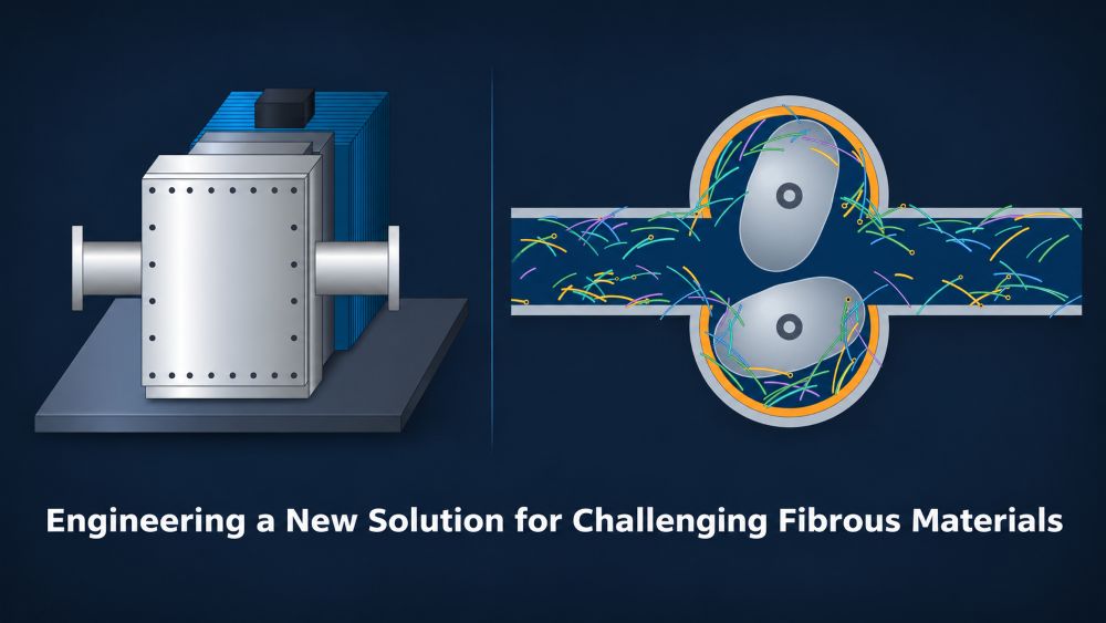
ENGINEERING DESIGN REPORT | REVISION 1 | 16 NOVEMBER 2026
Preliminary engineering design, mechanical concept development and prototype validation programme.
Document status: Preliminary engineering design. Not approved for manufacture.
1. Executive Summary
This project involves developing a new positive displacement pump designed to transfer high concentrations of fibrous materials.
The initial application involves partially shredded peacock feathers suspended in water and chemicals. The mixture contains 50% solids by actual displaced volume, with fibres up to 95 mm long.
The target duty is 209 L/min at a specified total dynamic head of 28 metres, operating continuously at approximately 43°C.
The pump will be developed to address six common limitations of conventional rotary lobe pumps:
- Abrasive wear of rotors and casing components.
- Internal slip and reduced volumetric efficiency.
- High maintenance and replacement costs.
- Limited dry-running capability.
- Fibre wrapping around rotors and shafts.
- Blockages caused by fibrous materials.
Rev 1 Design Direction
The proposed design is a low-speed, large-passage positive displacement pump incorporating specialised rotor geometry, replaceable wear components, independently supported bearings and engineered dry-running capability.
Dry running is a core design requirement. The pumping chamber, rotor materials, bearings and sealing arrangement will be developed to operate without relying on process liquid lubrication.
The permitted dry-running duration, speed and temperature limits must be established through prototype testing.
Primary engineering hold point: Demonstrate reliable suction conveyance and chamber filling with representative material before finalising the mechanical geometry.
2. Design Basis and Operating Requirements
| Parameter | Requirement |
|---|---|
| Application | Continuous fibrous material transfer |
| Pumped medium | Partially shredded peacock feathers |
| Carrier liquid | Water and unspecified chemicals |
| Solids concentration | 50% by actual displaced volume |
| Maximum fibre length | 95 mm |
| Reported viscosity | 5 cP, unverified |
| Operating temperature | 43°C |
| Required flow | 209 L/min |
| Specified total head | 28 m |
| Suction source | Agitated pit or sump |
| Minimum sump depth | Less than 300 mm |
| Suction lift | Less than 1 m |
| Suction pipe | 100 mm nominal, 1–3 m long |
| Discharge pipe | 100 mm nominal |
| Downstream pressure rating | Unknown |
| Electrical supply | 415 V, three-phase |
| Speed control | VFD |
| Preferred speed | 300–750 RPM |
| Wetted materials | 316 stainless steel preferred |
| Dry-running capability | Required design feature |
| Sealing | Seal-less preferred; protected shaft seals acceptable |
| Major overhaul target | 24 months or longer |
| Prototype | Full-scale, instrumented |
| Primary objective | Reliability and blockage prevention |
3. Engineering Assumptions
The following assumptions are used for preliminary calculations and must be verified before final equipment selection.
| ID | Assumption | Status |
|---|---|---|
| A01 | Reference density of 1,000 kg/m³ | Illustrative only |
| A02 | 28 m represents system head at duty flow | Requires verification |
| A03 | Actual pipe internal diameter is 100 mm | Unconfirmed |
| A04 | Mixture behaves homogeneously for preliminary calculations | Not demonstrated |
| A05 | Volumetric efficiency of 85% | Illustrative only |
| A06 | Overall pump efficiency of 50% | Illustrative only |
| A07 | 316 stainless steel is chemically compatible | Unverified |
| A08 | Solids measurement is repeatable | Requires validation |
| A09 | Dry-running-compatible materials can be developed | Requires testing |
| A10 | Heat generation during dry running can be controlled | Requires testing |
Important: A 50% true-volume fibrous mixture may exhibit yield stress, shear-dependent viscosity, fibre entanglement and non-uniform flow. Conventional Newtonian liquid calculations cannot establish actual pumpability.
4. Preliminary Hydraulic Calculations
4.1 Flow Rate
Q = 209 / 60,000 = 0.0034833 m³/s
| Parameter | Calculated Value |
|---|---|
| Flow rate | 209 L/min |
| Hourly throughput | 12.54 m³/h |
| Daily throughput | 300.96 m³/day |
| Annual throughput at 8,760 hours | 109,850 m³/year |
4.2 Suction Pipe Velocity
Assuming an actual internal diameter of 100 mm:
A = πD² / 4 = 0.007854 m²
v = Q / A = 0.444 m/s
| Internal Diameter | Velocity |
|---|---|
| 80 mm | 0.693 m/s |
| 100 mm | 0.444 m/s |
| 125 mm | 0.284 m/s |
| 150 mm | 0.197 m/s |
Larger pipes reduce velocity and conventional hydraulic resistance but may encourage fibre accumulation. Smaller pipes increase velocity but may increase suction resistance and fibre bridging.
No reliable critical transport velocity can be established without testing the actual mixture.
4.3 Differential Pressure
Using a reference density of 1,000 kg/m³:
Δp = ρ × g × H
Δp = 1,000 × 9.81 × 28
Δp = 274,680 Pa = 2.747 bar
4.4 Hydraulic Power
Ph = Δp × Q
Ph = 274,680 × 0.0034833
Ph = 957 W = 0.957 kW
This represents water-equivalent hydraulic power only. It does not establish the required motor rating.
4.5 Density Sensitivity
| Assumed Density | Differential Pressure | Hydraulic Power |
|---|---|---|
| 800 kg/m³ | 2.20 bar | 0.77 kW |
| 1,000 kg/m³ | 2.75 bar | 0.96 kW |
| 1,100 kg/m³ | 3.02 bar | 1.05 kW |
| 1,200 kg/m³ | 3.30 bar | 1.15 kW |
4.6 Shaft Power Sensitivity
Pshaft = Ph / η
| Assumed Overall Efficiency | Required Shaft Power |
|---|---|
| 30% | 3.19 kW |
| 40% | 2.39 kW |
| 50% | 1.91 kW |
| 60% | 1.60 kW |
| 70% | 1.37 kW |
These figures are illustrative and exclude unquantified startup, fibre compaction, blockage and transient loads.
4.7 Suction and NPSH Assessment
For a conventional liquid, available NPSH can be expressed as:
NPSHa = (Psurface,abs − Pvapour) / (ρg) + (Zsurface − Zpump) − hf,suction
This equation is only a preliminary reference. The fibrous mixture may not follow conventional liquid friction models.
The suction design must investigate:
- Air entrainment and vortex formation.
- Minimum suction inlet submergence.
- Fibre accumulation around the inlet.
- Loss of prime after shutdown.
- Inconsistent pumping chamber filling.
- The influence of sump agitation.
Critical design concern: The minimum sump liquid depth is less than 300 mm. Suction inlet geometry and minimum operating level must be validated before design approval.
5. Six Key Engineering Innovations
The following features define the proposed engineering development direction. Each requires prototype validation.
Innovation 1: Abrasion-Resistant Construction
Conventional limitation: Abrasive solids can cause wear to rotary lobe pump rotors and casings.
Proposed solution: Incorporate replaceable wear surfaces and durable rotor materials to minimise wear and simplify replacement.
- Replaceable casing wear liners.
- Removable wear-resistant rotor surfaces.
- Optimised internal surface finishes.
- Materials selected for abrasion and chemical compatibility.
- Individually replaceable high-wear components.
Validation: Measure wear rates, clearance changes and component condition during endurance testing.
Design objective: Engineered for Abrasion Resistance.
Innovation 2: Reduced Internal Slip
Conventional limitation: Internal leakage through pump clearances can reduce volumetric efficiency, particularly as components wear.
Proposed solution: Investigate optimised rotor profiles and replaceable clearance-control components.
- Optimised rotor geometry.
- Replaceable clearance-control components.
- Precision-machined internal surfaces.
- Wear-compensating features where feasible.
- Clearance restoration through component replacement.
Engineering consideration: Reducing internal slip and improving fibre passage may create conflicting requirements. Excessively tight clearances could increase the likelihood of fibre trapping and jamming.
Validation: Measure volumetric efficiency, internal leakage and blockage behaviour over the operating range.
Design objective: Optimised for Reduced Internal Slip.
Innovation 3: Low-Maintenance Modular Design
Conventional limitation: Worn rotors, seals and casing components can result in expensive repairs and extended downtime.
Proposed solution: Develop modular construction that allows individual components to be serviced or replaced.
- Quick-access front casing cover.
- Removable rotor assemblies.
- Replaceable casing liners.
- Externally accessible bearings.
- Modular shaft sealing components.
- Maintenance access without removing the complete pump.
Validation: Measure maintenance time, component replacement requirements and wear rates.
Design objective: Modular Design. Simplified Maintenance.
Innovation 4: Engineered Dry-Running Capability
Conventional limitation: Many rotary lobe pumps rely on the pumped liquid for cooling or lubrication of certain components. Dry operation can result in seal damage, excessive wear and overheating.
Rev 1 design requirement: The new pump will be specifically engineered to operate dry without immediate damage to its pumping chamber, bearings or sealing components.
Dry-running capability will be developed through a combination of material selection, mechanical isolation, lubrication design, clearance control and thermal management.
Dry-Running-Compatible Rotor Materials
Rotor and casing surfaces will be selected to minimise friction, galling and wear without relying on process liquid lubrication.
Independently Lubricated Bearings
Bearings will be positioned outside the wetted chamber and lubricated independently of the pumped medium.
Protected Shaft Sealing
A seal-less drive or independently lubricated and cooled mechanical sealing arrangement will be investigated.
Low-Friction Internal Geometry
Rotor profiles and clearances will be developed to minimise unintended mechanical contact and excessive heat generation during dry operation.
Thermal Management
The design will account for heat generation, heat dissipation and thermal expansion during dry-running conditions.
Temperature Monitoring
Temperature sensors will provide additional protection against operation beyond the validated thermal limits.
Restart Capability
The pump will be designed to restart following a permitted dry-running event without requiring replacement of internal components.
Dry-Running Performance Requirements
- Operate without process liquid lubrication for a defined period.
- Prevent unacceptable rotor and casing wear.
- Prevent unacceptable shaft seal damage.
- Maintain controlled bearing and casing temperatures.
- Operate within validated dry-running speed limits.
- Restart successfully after a permitted dry-running event.
- Maintain acceptable performance following repeated wet-to-dry cycles.
Validation: Controlled prototype testing will establish the maximum permitted dry-running duration, speed, temperature and restart conditions.
Important: Engineered dry-running capability does not imply unlimited dry operation. The allowable operating envelope must be demonstrated through testing.
Design objective: Designed to Run Dry.
Innovation 5: Anti-Wrapping Rotor Technology
Conventional limitation: Long fibrous materials can wrap around rotating shafts and pumping elements, causing increased torque, loss of flow and mechanical damage.
Proposed solution: Develop rotor geometry that reduces exposed shaft surfaces and potential fibre entanglement points.
- Smooth, rounded rotor profiles.
- Shielded or recessed shaft entry points.
- Reduced exposed rotating shaft surfaces.
- Generously radiused internal transitions.
- Reduced internal pockets and projections.
- Non-cutting rotor geometry.
Validation: Test representative fibres up to 95 mm long for wrapping, entanglement and rotor jamming.
Design objective: Designed to Prevent Fibre Wrapping.
Innovation 6: Anti-Blockage Flow Design
Conventional limitation: Fibrous materials can accumulate at inlets, rotor clearances and internal restrictions, resulting in blockages.
Proposed solution: Develop a large-passage pumping chamber with smooth transitions and reduced internal restrictions.
- Large, unobstructed inlet passages.
- Smooth inlet-to-chamber transitions.
- Reduced internal flow restrictions.
- Rotor geometry designed to minimise fibre trapping.
- Reduced dead zones and accumulation pockets.
- Torque monitoring for developing blockages.
- Suction pressure monitoring to detect poor chamber filling.
Validation: Conduct full-scale suction and pumping trials using the actual 50% solids mixture.
Design objective: Engineered for Blockage Resistance.
6. Preliminary Mechanical Configuration
6.1 Preferred Prototype Architecture
A twin-rotor positive displacement arrangement is the initial mechanical development baseline. The final pumping mechanism remains subject to testing.
| Component | Preliminary Design Intent |
|---|---|
| Casing | 316 stainless steel with accessible cover |
| Rotors | Smooth-profile, replaceable components |
| Timing gears | Externally mounted |
| Bearings | Externally supported and independently lubricated |
| Sealing | Seal-less or independently protected arrangement |
| Wear protection | Replaceable internal surfaces |
| Drive | Geared electric motor with VFD |
| Maintenance | Accessible rotor and casing assembly |
| Dry-running design | Low-friction materials and thermal management |
6.2 Pump Displacement
Vd = Q / (N × ηv)
Using an illustrative volumetric efficiency of 85%:
| Speed | Required Theoretical Displacement |
|---|---|
| 150 RPM | 1.639 L/rev |
| 200 RPM | 1.229 L/rev |
| 300 RPM | 0.820 L/rev |
| 450 RPM | 0.546 L/rev |
| 600 RPM | 0.410 L/rev |
| 750 RPM | 0.328 L/rev |
Speeds below the preferred range should also be investigated to determine whether reduced fibre entanglement improves reliability.
6.3 Shaft Torque
T = 9,550 × Pshaft / N
At an illustrative shaft power of 1.91 kW:
| Speed | Indicative Shaft Torque |
|---|---|
| 150 RPM | 121.6 Nm |
| 200 RPM | 91.2 Nm |
| 300 RPM | 60.8 Nm |
| 450 RPM | 40.5 Nm |
| 600 RPM | 30.4 Nm |
| 750 RPM | 24.3 Nm |
Final shaft sizing requires actual torque measurements, rotor geometry, bearing loads and transient load assessment.
6.4 Shaft Design
For a solid circular shaft under pure torsion:
τmax = 16T / (πd³)
Final shaft calculations must also consider combined bending, fatigue, stress concentrations, shaft deflection, rotor loads, keyways and jam torque.
6.5 Bearings and Service Life
The 24-month major-overhaul target corresponds to approximately 17,520 operating hours.
Bearing selection must consider actual dynamic loads, axial and radial forces, speed, lubrication, temperature and required reliability.
6.6 Materials and Thermal Design
316 stainless steel is a preliminary candidate material, subject to chemical compatibility assessment.
The design must account for thermal expansion at 43°C, temperature rise during dry running, galling between metallic components, abrasive wear and compatibility of any seals, liners or coatings.
7. Pump Technology Comparison
Rotary Lobe Concept
Provides accessible pumping chambers, external rotor synchronisation and opportunities to investigate large-passage rotor geometry.
Principal risks include fibre wrapping, rotor jamming, internal leakage and wear.
Progressive Cavity Concept
May handle cohesive mixtures, but suction filling, stator wear, fibre entanglement and dry-running limitations require investigation.
Peristaltic Hose Concept
Offers an isolated wetted flow path, but hose recovery, suction performance, fibre passage, dry-running heat generation and hose life remain uncertain.
| Criterion | Rotary Lobe | Progressive Cavity | Peristaltic |
|---|---|---|---|
| Long-fibre handling | Unverified | Unverified | Unverified |
| Suction filling | Requires testing | Requires testing | Requires testing |
| Seal-less wetted path | Difficult | Difficult | Possible |
| Dry-running capability | Requires engineered solution | Requires engineered solution | Requires hose and thermal validation |
| 24-month overhaul target | Unverified | Unverified | Unverified |
| Blockage resistance | Unverified | Unverified | Unverified |
The rotary lobe arrangement remains the initial mechanical baseline, not a confirmed pump selection.
8. Control and Instrumentation
| Tag | Instrument | Purpose |
|---|---|---|
| LT-101 | Sump level transmitter | Level monitoring |
| PS-101 | Suction pressure transmitter | Detect poor filling |
| PT-102 | Discharge pressure transmitter | Pressure monitoring |
| FT-101 | Flow meter | Flow verification |
| ST-101 | Speed sensor | RPM monitoring |
| TT-101 | Temperature sensors | Thermal protection |
| VT-101 | Vibration sensor | Condition monitoring |
| TRQ-101 | Torque sensor | Mechanical loading |
| VFD-101 | Variable frequency drive | Speed control |
| PSV-101 | Independent pressure relief | Overpressure protection |
8.1 Operating Sequence
- Confirm sump level and agitation.
- Verify discharge path and pressure protection.
- Start at an approved low speed.
- Verify suction filling and flow.
- Increase speed to achieve the required duty.
- Monitor torque, pressure and temperature.
- Stop safely if an abnormal condition occurs.
8.2 Dry-Running Control Philosophy
Dry running will be a permitted operating condition within a defined and tested operating envelope.
A low-flow condition will not automatically be treated as immediate mechanical failure. The control system must distinguish between approved dry-running operation and conditions that exceed permitted thermal or mechanical limits.
- Dry-running mode indication.
- Speed limitation during dry operation.
- Temperature-based protection.
- Torque monitoring.
- Dry-running duration monitoring.
- Automatic shutdown at validated limits.
- Controlled restart following dry operation.
The allowable duration, speed and temperature limits will be established through testing.
9. Safety and Reliability Assessment
| Failure Mode | Consequence | Proposed Safeguard |
|---|---|---|
| Fibre bridging | Loss of flow | Flow and suction monitoring |
| Rotor jamming | Mechanical damage | Torque monitoring and trip |
| Blocked discharge | Overpressure | Independent pressure relief |
| Excessive dry-running temperature | Thermal damage | Temperature monitoring and shutdown |
| Agitator failure | Solids accumulation | Agitator interlock |
| Seal failure | Process leakage | Seal monitoring and containment |
| Bearing failure | Mechanical seizure | Temperature and vibration monitoring |
| VFD malfunction | Uncontrolled operation | Independent safety functions |
| Relief path blockage | Loss of protection | Validated solids-compatible relief design |
| Insufficient sump submergence | Air entrainment | Level monitoring |
Pressure safety: A VFD current limit is not a substitute for independent overpressure protection. Relief capacity and routing must be engineered for the maximum credible pump delivery and fibrous process medium.
The final design requires a formal machinery risk assessment addressing pressure containment, electrical safety, moving parts, maintenance, isolation, chemical exposure and foreseeable abnormal operation.
10. Full-Scale Prototype Test Programme
Phase 1: Material Characterisation
Determine mixture density, fibre distribution, solids fraction, rheology, chemical properties and repeatability of sample preparation.
Acceptance: Representative test material can be prepared and measured consistently.
Phase 2: Suction Conveyance
Test the actual suction lift, 1–3 m pipe length and minimum sump operating level. Compare alternative pipe diameters where necessary.
Acceptance: Stable conveyance without persistent bridging, unacceptable vacuum or loss of prime.
Phase 3: Hydraulic Performance
Measure flow, differential pressure, speed, torque, electrical power and temperature across the operating envelope.
Acceptance: Demonstrate 209 L/min at the verified system duty without exceeding approved operating limits.
Phase 4: Dry-Running Validation
Conduct controlled dry-running tests to establish the permitted operating envelope.
Investigate:
- Dry operation at different speeds.
- Temperature rise over time.
- Rotor and casing wear.
- Seal and bearing temperatures.
- Torque and power consumption.
- Thermal expansion and internal clearances.
- Repeated wet-to-dry transitions.
- Restart following dry operation.
Acceptance: Demonstrate operation without process liquid for a defined duration and speed without unacceptable component damage, thermal excursion or loss of subsequent pumping performance.
The final allowable dry-running duration and operating limits will be established from measured results.
Phase 5: Protective Function Testing
Verify high-pressure, high-torque, temperature, loss-of-flow and agitator-failure responses using controlled fault simulations.
Acceptance: The pump reaches a safe state without exceeding approved limits.
Phase 6: Endurance and Wear
Conduct extended operation with scheduled inspection of rotors, clearances, shafts, bearings, seals and wear components.
Acceptance: Document evidence supporting the intended 17,520-hour major-overhaul target.
10.1 Prototype Data Recording
| Measurement | Units | Recording |
|---|---|---|
| Flow | L/min | Continuous |
| Suction pressure | kPa absolute | Continuous |
| Discharge pressure | bar | Continuous |
| Speed | RPM | Continuous |
| Torque | Nm | Continuous |
| Electrical power | kW | Continuous |
| Mixture temperature | °C | Continuous |
| Bearing temperature | °C | Continuous |
| Dry-running duration | Seconds/minutes | Each event |
| Rotor temperature | °C | As measurable |
| Vibration | mm/s RMS | Defined intervals |
| Solids concentration | % by volume | Each batch |
| Blockage events | Count | Event log |
| Component wear | mm | Inspection intervals |
11. Engineering Hold Points
The following requirements must be resolved before the final design is approved for manufacture.
- Validate the 50% solids measurement and material properties.
- Identify chemicals and confirm material compatibility.
- Confirm downstream maximum allowable pressure.
- Establish actual system pressure versus flow.
- Verify sump geometry and suction submergence.
- Demonstrate suction conveyance.
- Select and test the pumping mechanism.
- Measure operating, starting and jam torque.
- Complete rotor, shaft and bearing calculations.
- Select dry-running-compatible materials.
- Validate dry-running thermal performance.
- Establish permitted dry-running duration and speed.
- Verify seal and bearing protection during dry operation.
- Validate independent pressure protection.
- Complete machinery safety assessment.
- Approve prototype acceptance criteria.
12. Design Deliverables Register
| Document | Status |
|---|---|
| Design basis and duty specification | Preliminary |
| Hydraulic calculations | Preliminary |
| Pump concept comparison | Preliminary |
| Six innovation design requirements | Defined for development |
| General arrangement drawing | Not started |
| Rotor and casing manufacturing drawings | Awaiting tests |
| Shaft and bearing calculations | Awaiting geometry |
| Motor and gearbox specification | Awaiting torque data |
| Materials and sealing specification | Awaiting compatibility review |
| Dry-running thermal design | Awaiting development |
| Instrumentation and control philosophy | Preliminary |
| P&ID and pressure protection design | Not completed |
| Machinery risk assessment | Not completed |
| Prototype test procedure | Preliminary |
| Dry-running validation report | Awaiting testing |
| Prototype performance report | Awaiting testing |
| Endurance and reliability report | Awaiting testing |
| Final design verification and approval | Not completed |
13. Recommended Development Sequence
- Material and suction feasibility: Validate mixture properties and suction conveyance.
- Mechanical concept selection: Compare pumping mechanisms using representative material.
- Detailed mechanical design: Develop rotor geometry, shaft loads, bearings, sealing and casing construction.
- Dry-running design development: Select materials, lubrication arrangements, clearances and thermal management features.
- Prototype manufacture: Build the selected configuration.
- Performance and dry-running testing: Validate hydraulic duty, mechanical performance and permitted dry-running conditions.
- Design verification: Resolve test failures, complete risk assessments and approve the final design.
14. Engineering Conclusion
The proposed pump development programme aims to address six major limitations of conventional rotary lobe pumps.
The Rev 1 design incorporates engineered dry-running capability as a core development requirement, alongside improved wear resistance, reduced internal slip, modular maintenance, anti-wrapping rotor geometry and blockage-resistant flow passages.
Preliminary calculations establish a water-equivalent differential pressure of approximately 2.75 bar and hydraulic power of approximately 0.96 kW.
These calculations do not establish actual shaft power, motor rating, mechanical dimensions or dry-running limits.
The principal engineering uncertainties remain suction conveyance, chamber filling, fibre entanglement, transient torque, component wear and thermal performance during dry operation.
Recommended Next Action
Use the fully instrumented prototype test facility to validate suction conveyance, pumping performance and dry-running behaviour.
The results will determine the mechanical design direction and establish the permitted operating envelope.
Last Updated on November 20, 2026 by TPE